Tuesday, April 22, 2014

DIY CNC Build in Switzerland - Building the X and Z axis carriage - Part 2

Again a long break:) I have started working on the CNC project again. This will be actually a really long post. I have done quite a lot. So lets start asap.

As I mentioned in earlier posts I needed to support the gantry from sides so that it would be stiff enough for the bending forces that may occur. I used aluminum sheet and cut the rectangles based on my updated design. To mount this plate, I did not use the fancy aluminum extrusion mounting stuff. Instead, I drilled all the way through the extrusion and used a M5 screw and nut to keep the plate in place.


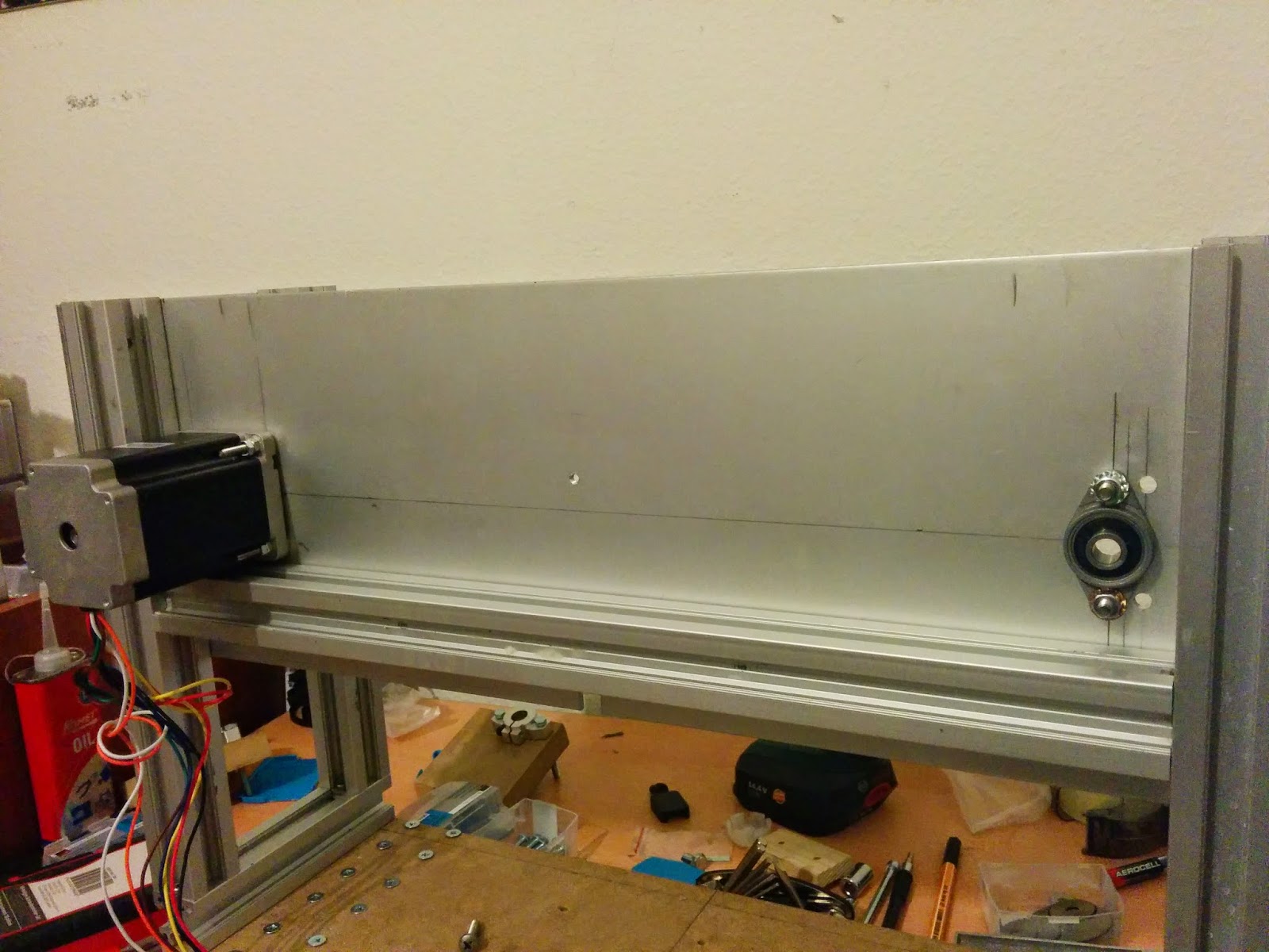
 Also for the back side of the gantry, I needed something for the support and motor mount. So again used aluminum plate. Below you can see the final assembly. The problem here was to decide the places for the holes so that nothing will interfere with each other.


Now comes the worst part:) In the last picture of the previous post I have just showed you how the x axis would look like. You may have realized that the steel rods are not long enough to mount to the side aluminum plates of the gantry. I have ordered a precise cut to my original design lengths and as I have updated my design. I have a 13 mm gap from each side:) Nice, right? So I needed some kind of riser blocks between the side plates and the shaft supports. I needed something strong so I used MDF. The problem here is that the movement of X Axis is parallel to the holes. This is ok but the weight of the Z axis and Z axis forces that will occur while miling something are perpendicular to the bolt direction. SO, I could not simply use an ordinary riser or a little piece of block as it would all together bend. That is why we need to fill the gap between aluminum extrusions as much as possible.

 In order to mount the risers, I needed to disassemble whole gantry. The holes must be error free and incredible accurate. Couple of degrees error during drilling the MDF would lead to disaster on the miling surface as it would be magnified along the X Axis.

 I started one by one mounting the risers and the shaft supports for the steel rods of X axis. Without mounting the back plate and aluminum extrusion, I did a test fit with the X Axis base plate. It looked good to me and I decided to continue although I had 0.63 mm error on the right side. While I was drilling I forgot to tap a guide mark on the aluminum and drill wanted to move 0.63mm down. Below are pictures from different angles.


Again, one step back:) In order to drill the motor mount and belt drive holes, I needed to disassemble the back plate. Actually, the test fitting was very helpful as I re-measured the distances for where I have to drill. Below picture with 4 holes is for motor mount and picture with 2 holes is for pillow block bearing that holds the belt drive pulley.


I started again mounting the things together. First I mounted the plate, then the back aluminum extrusion.

 Now it is time to mount the X axis motor. I decided to try motor itself without building a gearbox. Using a gearbox is really painful. It is very hard to align the gears after drilling the holes and it is too NOISY. As this is my first CNC, I am trying the easiest way first, if it does not work, I will rework on it;) So to mount the motor, I measured the hole sizes from the motor and tapped it with M5. I have no problem to ruin my motors:)


 Time to mount the motor... There is a bevel on top of the motor for standard mount brackets. To compensate this bevel, I used simply 4 washers between the plate and the motor. Please note that the washer height must be exactly the height of bevel and it should not be a large washer.


 Using a drill would help you as you get tired mounting/unmounting things:)

 Now time to mount the billow block bearing for the X axis belt drive.


 The pillow bearing I used has an inner hole diameter of 8mms. I have used just ordinary aluminum rod as it is not that important to use steel rod. I have already got steel hardened 8mm rod but i used aluminum. You may say aluminum is not strong enough but the length I used is 40mm and only 10mm is out of bearing which is used to hold pulley. Also the nature of the movement is that we have a rotation and the force applied by the belt tension is applied to all the sides of the aluminum rod during rotation. So I HOPE IT WONT BEND:)


So final assembly looks like below with and without pulley...

 I have done just a test fit of pulleys and belt(with clamp) to see the movement axis better.

 
So now the fun part:) building the Z Axis carriage. I started with the exact same size of MDF I used for Y axis carriage. This helped me a lot during aligning the linear bearings to Y axis. I needed to drill the holes to mount the Z axis motor on the X axis plate. I marked them and drilled with the drill press. Here again I needed washers to compensate the motor bevel. For the motor shaft hole I used 10mm drill bit so it would move easily with 2 mm clearance as the motor shaft has 8mm diameter.


 Now, I needed to drill the holes for the pillow block bearing for the pulley of Z Axis. I have such a great design that I used the shaft support holes to mount pillow bearing:) No need for extra holes.


Time to mount the motor.

Time to build the pulley shaft for Z axis. Again 8mm aluminum rod...


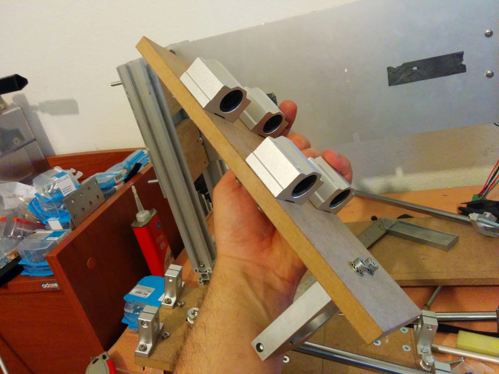
 To visualize how linear bearings fit, below are a couple of pictures before the real mounting.

 Now, from MDF I marked the holes for linear bearings for Z axis carriage and drilled them with drill press.


 I counter sunk the holes so screw heads will be flush with the surface. Now, mounting the linear bearings to Z carriage.

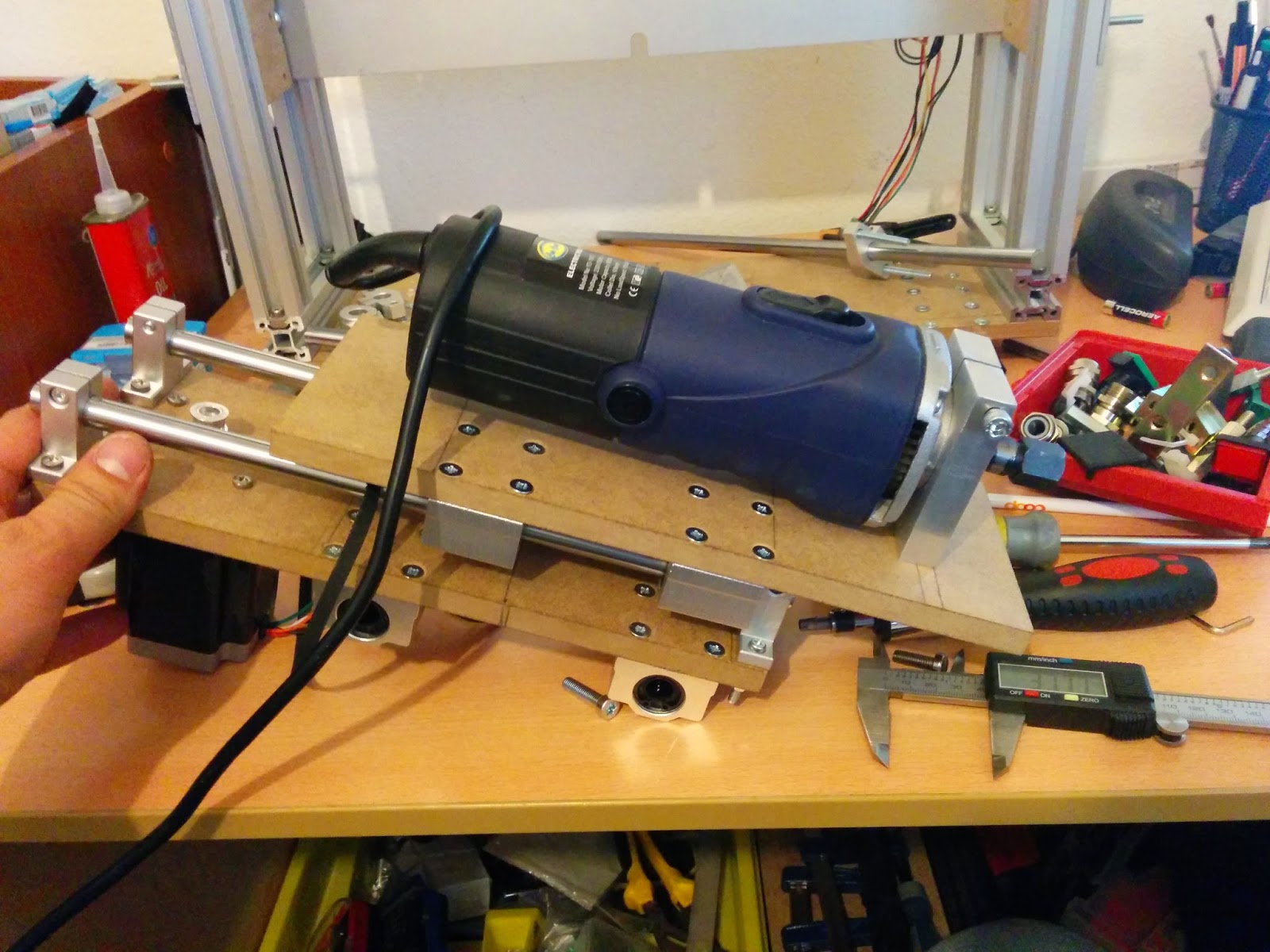
 I mounted the spindle mount as well. See below.

 Now time to assemble Z carriage with X axis. The most tricky part is to bind the belt to Z carriage. For this I need exact space between the X and Z carriages. I will show this in the next post.


 And here is the final assembly.

Hope you are enjoying the posts. Make a comment if you would like to see something in detail. See you next time....


Thursday, April 10, 2014

DIY CNC Build in Switzerland - Building the X and Z axis carriage - Part 1

I am back:) After a long break, I got back to working on my CNC again. And started with a failure:D In order to create my X and Z axis I bought a 100X100x10mm aluminum plate and failed to cut it according to my design. It is incredibly hard to cut that thick aluminum precisely if you do not have big machinery like me. I have no professional tools to cut that thick aluminum. So I decided to create my CNC first from MDF then use it to cut its parts itself:) This is actually cool as you create one a working CNC, you can machine its own parts:)

So lets begin...
I have used a 12mm MDF board for X axis carriage and created a paper template. I used Pritt to glue it on the MDF for drilling holes. You can use Inkscape program to create your one to one templates and print using it. The linear bearing would look like as below after mounting. Using drill press all the holes are drilled.


After drilling the holes, check of alignment of linear bearings is necessary. Linear bearings has M5 holes for the screws. I usually drill one size bigger. Here I drilled M6 so I have some space to compensate error. When you tighten the screws the size would not affect actually.


Now it is time to cut steel hardened rod according to my needs for the Z axis carriage which will actually reside on X axis. After cutting it, I always try a test fit as you can see below. I use 12 mm steel rod and shaft supports for the Z axis-


Now we are ready to screw everything in place.I realized that the money that I paid to screws and bolts is getting bigger and bigger:D


 Finally, I looks like this at the end of mounting the linear bearings, rods and shaft supports.

Here is a picture to visualize all the things in place.
Next is building the mount to gantry and motor mounts for X and Z:)

Tuesday, April 1, 2014

DIY CNC Build in Switzerland - Building the motor mount, gear box and belt drive for Y Axis

I have been searching for options to build the linear motion drive either with lead screws or belt drive. In Switzerland, building a CNC with lead screws (or even ball screws) is incredibly expensive. This is my first try so I did not want to invest a lot:) I decided to use belt drive for all axis. Belt drive is not also cheap when you consider the pulley and belt price. Usually for CNCs 12 mm width (or more) belt is used but the pulleys and belts are expensive again. So I decided to try something: use two 6 mm GT2 belt pulley system in each axis. A short summary of belts systems for you(from RepRap wiki):

T5
These are asynchronous metric timing belts. They have trapezoidal teeth and deliberate backlash to reduce belt wear and noise for uni-directional applications. They are difficult to get in North America. The pulleys themselves though can be printed. Using a printed pulley will give you approximately the same results as if you use an MXL pulley/belt combination with the wrong bore size.
T2.5
Like the T5 these are asynchronous metric belt/pulley combinations. These have a 2.5mm (.098") pitch and are printable. With the same diameter pulleys there is a better grip (compared to t5) on the belt and will give a better result. The best results are with metal pulleys due to the fine tooth profile.
MXL
This stands for "mini extra-light". These belts have been around since the 1940s. Like T5 & T2.5, these are also asynchronous timing belts but they are common in North America because they use imperial sizes. The distance between teeth is 0.08" and the teeth are trapezoidal. You *may* be able to find pulleys that have a 5mm bore but it seems difficult. Most stepper motors have spindles that are 5mm in diameter.
HTD
This stands for "high torque drive" and was introduced by Gates in 1971. These belts have less backlash than MXL and T5 belts because the teeth are deeper and are rounded. These belts were originally patented by Gates but the Patent has since expired.
GT2
These are Gates PowerGrip® GT®2 industrial synchronous timing belts. GT stands for "Gates Tooth". GT2 came about because the HTD patents ran out and they needed a new tooth profile that was not public domain. Gates says the GT2 belts will run OK on HTD pulleys but not the other way around. GT2 belts are stronger than HTD belts, but they need the GT2 tooth profile on the pulleys to achieve their ultimate strength advantage over HTD. These may be more difficult to find everywhere.
Spectra
Spectra fiber braided fishing line is quickly becoming a popular choice to replace belts in many applications after its first implementation in Tantillus and then in many Delta printers. It is cheap and available in most cities around the world. Once tightened correctly it has almost no backlash and provides very smooth movement due to the lack of bumpy teeth and its incredibly small bend radius allowing high steps per mm.
In summary, for best performance at least 6 teeth must be in contact with the pulley at any given time. That minimizes the chance of the belt slipping, and helps reduce backlash even further.Beyond that minimum, fewer teeth are generally better than more teeth, since a smaller pulley gives both more torque and more resolution. So I bought GT2 belt and pulleys for $40 in total:)

Lets start building the motor mount:

For the motor mount I have tried to use Acrylic plate but I could not find a plate of 10 mm thickness as this was required to embed the bearings. So I decided to use MDF. If you have access to HDF, use it as it is stronger. And a tip for you never drill MDF from the side(10 mm side). MDF is built in factories by pressing layers of wood particles. So it is strong from the faces not from the side


I marked the motor mounting points so I could use a threaded rod to mount all three plates around the motor.


I have got Nema 24(Yes:) that is 24 not 23). This motor has 485oz/inc torque. The top of the motor has a 37 mm circle bevel so I needed to use the fly cutter to cut a deep groove in the MDF.

I could have directly mount the belt to the motor as it is strong enough, but I would like to mill mild steel as well at the end so I decided to use around 1/7 gear reduction. As you may see in youtube or on web, reduction on belt drive systems are done again with pulleys and belts, which is too expensive for me to invest:) So I decided to build my gear box on top of the motor. I found matching gears and just drilled them to 8mms which is the size of the motor shaft.


For mounting the gear, I decided to use set screws, I have unfortunately M3 taper smallest. So I decided to use M3 as set screw size.


The ball bearing will be the shaft for the big gear. I needed to embed it into MDF. I used the fly cutter to cut 7mm deep grove and pushed the bearing inside.


The motor mount was not tapped but the width was perfect for M5. So I tapped it:)

 When all the pieces were ready as shows above, I started assembly.


Next is mounting it to gantry. To mount the block to gantry, I drilled holes into sides of MDF and drilled a hole on the face and pushed a nut there. If you use wood screws on MDF it may break, be careful. So I solved it like below.


Here is a video of testing motor block only.


 Here is a very very very:) primitive test with clamps holding the belt in place.